The Idea
There are many situations when you miss a delivery or a visitor while being in the garden, garage, workshop or just watching a movie or listening music.
Of course, there are wireless doorbell extenders, but I prefer system solution. The idea is simple, to integrate the standard wired doorbell into my sensor network so each doorbell ring generates MQTT message as any other sensor.
Then there are unlimited options how to utilize the doorbell events. And we can easily test them using a simple Node-RED flow. To send an SMS, to activate some light effect on a LED strip or sound on an external alarm.
The Solution
Well, the success of any solution depends on the ability to find the best solver for the particular task. And in this case, I was absolutely positive I am not the one. So I raised my question in the BigClown forum.
I am not sure what I really expected but I got more than dreamed of. Not only perfect solution for this one task but also nice adventure, some understanding of several electronic components and in overall big motivation to cope with similar challenges in future.
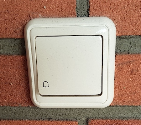
The Doorbell
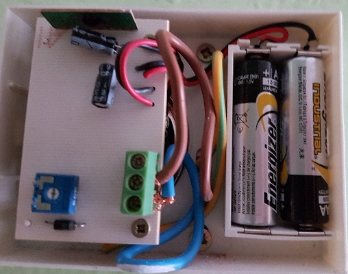
The first task was to understand how the existing doorbell works. After short investigation, it was clear that there is an electronic part with speaker powered by AA batteries and The Doorbell electric circuit connecting the 8V output of Bell transformer to the Doorbell button and then to the Gong. The current in the 8V circuit triggers the electronic Gong.
 |
 |
Initial Idea, resistor-optocoupler circuit
I feel like there are some far memories of resistor and ohm law hidden somewhere deep in my brain. But I am not sure I want to touch them today. Considering electric current flows as water (sorry guys, this is kindergarten course of electronic) I take resistor as a tap.
When slightly turned on, it has a high resistance and permits only a small flow, when is turned on more, a lower resistance permits more powerful flow. And we need to limit the flow to a level which our tiny optocoupler can bear.
To be honest I never heard of optocoupler before and now I imagine it as sort of button in one electric circuit which can be switched on by light emitted by a LED in another circuit.
Fortunately, there is the Button module as one of the standard BigCLown building blocks so you can easily build your own remote button combining it with the Core and Battery modules.
In fact, we are not going to use the Button module itself but we benefit from its existing setup in the BigClown ecosystem. So when we replace it with our optocoupler, it will work without touching any piece of software.
First experiment
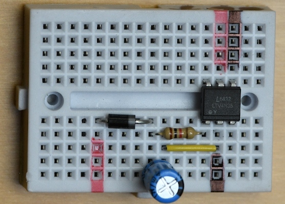
So far the theory, time to start experimenting to see whether it really works. Fortunately, I got an Arduino started kit with plenty of various parts so after some investigation I was able to put together my testing playground. There is the optocoupler 4N35 connected in the center of the mini breadboard
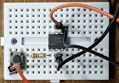
splitting the breadboard into two isolated circuits. The bottom one represents the 8V Doorbell circuit where the small switch in the bottom left corner simulates the doorbell button. 1k Ohm resistor limits the current to the optocoupler. Wiring follows the connection schema for the optocoupler 4N35.
The top one with the optocoupler button function is directly connected to the Core module following the connection schema for the Button module. The red wire is live, the black is ground.
To simulate the doorbell circuit I used 5V from Arduino and the whole picture of the testing environment is here.
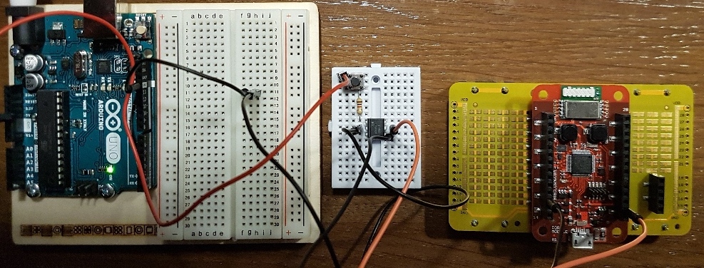
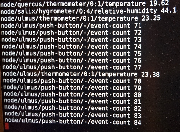
Surprisingly, it was easy as that, the test was successful, every button push generated a push-button event.
Semi-production
I took it as a sign to start experiments in real conditions. Replacing the Arduino circuit with a real doorbell circuit. Bypassing the small button on the breadboard as his role was overtaken by the real doorbell button. Making sort of semi-production environment.
 |
 |
Some troubles
Excited, and eager to succeed, laptop with mosquitto client in one hand, the second hand pressing the doorbell button. The first doorbell push was promising. The event was there but after that nothing at all.
I switched back to my original testing setup to check whether everything is still okay, and everything worked perfectly. So I rearranged semi-prod and started more thorough testing.
The problem was with the standard short press. It generates event only very rarely. But with a long press, it always generated a couple of events with the count depending on the press duration.
It was time to consult with the experts again. The root cause seems to be the alternating 8V current coming from the bell transformer.
Half wave rectifier
The suggested fix was to build so-called «half wave rectifier» and place it in front of the resistor-optocoupler set. The intention is to rectify the alternating current. Using two electronic components. The first is a diode which passes just one half of the wave of the AC supply. The second is a capacitor which smoothes the remaining half waves of the current by storing the energy within the peak and releasing it during the steady part. Like in the picture below.
The final set, extended by adding the diode and electrolytic smoothing capacitor 100 uF, is here:
Then back in semi-production, left hand holding the laptop, right hand pressing the doorbell button. Excitement like few moments before Falcon Heavy first launch.
The Success
YES!! It worked perfectly this time. Exactly one event for any press, short or long, any duration, no gaps. It’s amazing. I am so proud of myself. I created something really functional with my own hands, even though driven by expert advice.
More thorough testing showed that in case of quick double or triple click on the doorbell button there is only one event. But in fact, that’s optimal behavior for my purpose. In case of requirement to exactly reproduce any special signal on the doorbell button like the morse code, more precise selection of capacitor is needed. Expert advice is to use a 47uF capacitor, but I am happy with my 100uF capacitor from the Arduino starter kit.
The Production
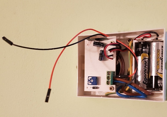
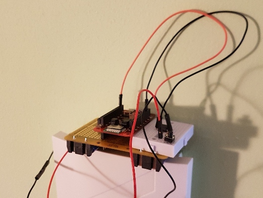
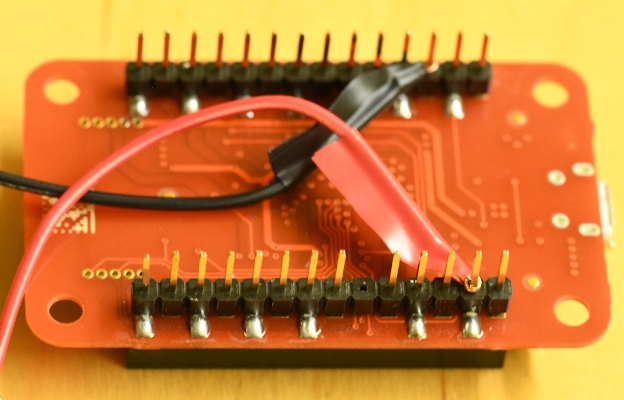
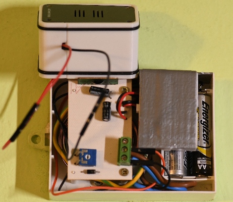
Now there is the last task, to productionize the result. I had just two main requirements. The first, to place the newly constructed electronic set into the existing Gong and then connect it to an external box containing BigClown mini-battery and core modules. The second, to keep the maintenance easy as possible, so replacing batteries in both Gong and BigClown box without any special effort.
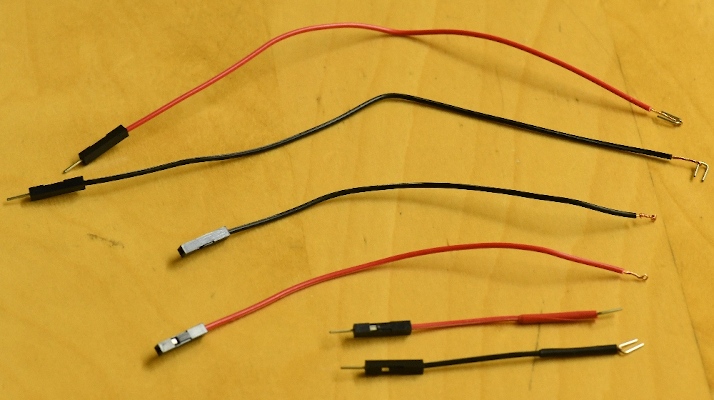
First I customized some of the wire terminations, making a loop to connect to the core module, and a fork to plug into the breadboard
 |
 |
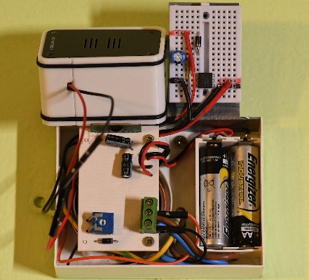
Then I put all the parts together, utilizing a drawbridge pattern to make the gong batteries easily accessible.
 |
 |
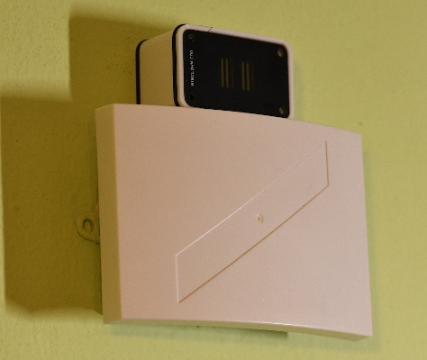 |
The final test was also successful and this new equipment is already in daily use. The first week of careful observation didn’t reveal any functional issue. DIY Rules!